To automate the processes of turning on, reversing and turning off three-phase electric motors, an electromagnetic starter 220 V or 380 V is used. The device is only compatible with asynchronous motors, the supply voltage of which is no more than 600 V. Before connecting it, it is necessary to select and study the circuit correctly.
- Areas of use
- The principle of operation of the electromagnetic starter
- Device device
- Features of the design of the starter
- Sector designations
- Contact groups of the magnetic starter
- Stop key
- Start key
- Device types
- Design versatility
- Electric starters with thermal relays
- Degree of protection
- Subtleties of connecting a 220 V device
- Classic
- Power circuit specifics
- How to change the control circuit
- Connection to a three-phase network
- Service specifics
Areas of use
The purpose of the electric starter is to start, stop and reverse motors. The device is also suitable for controlling the lighting line, specialized equipment - pumps, air conditioners, conveyor belts, compressors.
Despite the fact that the contactor has supplanted the device, it is used in manufacturing or communication systems.
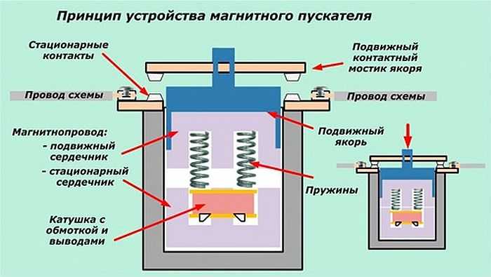
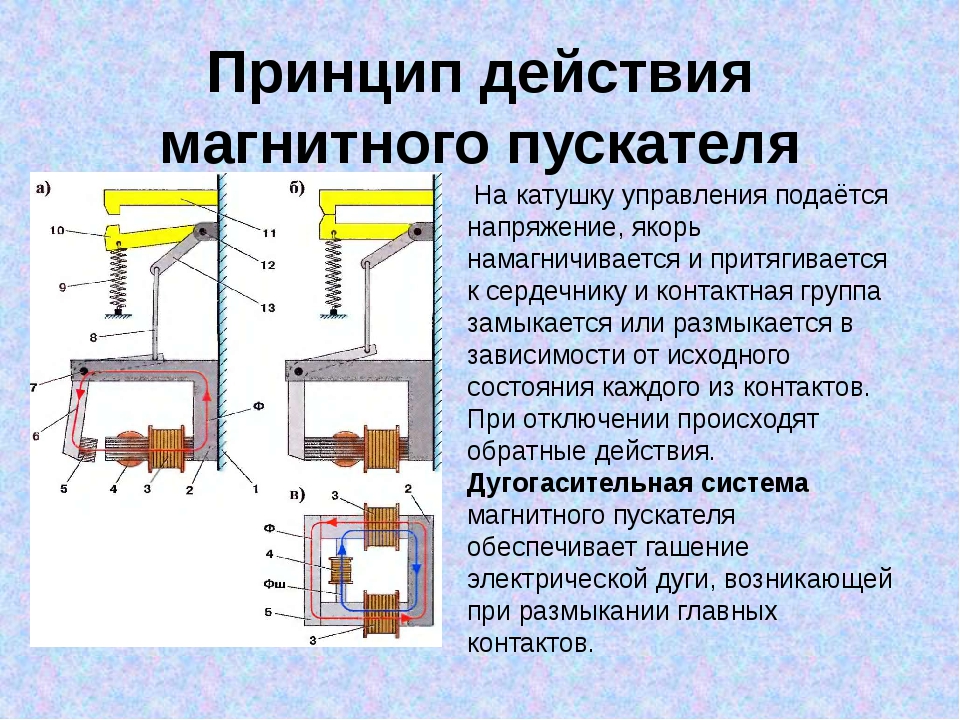
The principle of operation of the electromagnetic starter
Start and stop buttons are used for control. The automatic device has a simple algorithm of action:
- Applying voltage to the active coil.
- The formation of a magnetic field around the element.
- Pulling inside a metal core with metal contacts fixed.
- Closing the power contacts - the current is supplied to the load.
The reverse is carried out using a coupler of two starters.
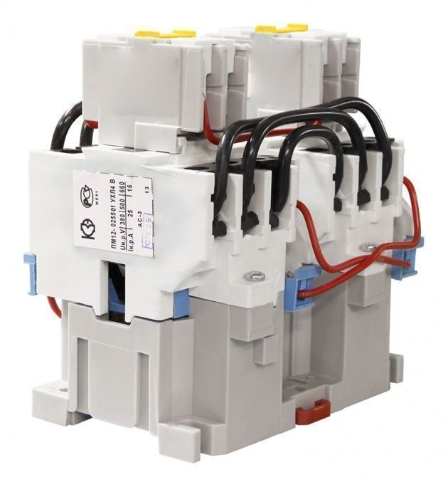
Device device
- core;
- coil of electromagnetic type;
- anchor;
- connecting frame;
- mechanical type sensors;
- central and auxiliary contactor system.
Additional components of the device may include electrical fuses, an additional set of terminals, a start device and a protection relay.
Features of the design of the starter
Sector designations
The principle of operation of the device can be understood from the information from the sectors:
- in the first, fields of application and general data are indicated - alternating frequency, current rating and conventional thermal current;
- from the second sector, you can find out the maximum load power when connecting the power contacts;
- in the third sector there is a graphic diagram with an electric magnet coil and contacts.
By the presence of a dotted line from the coil to the contacts, you can determine their synchronization of action.
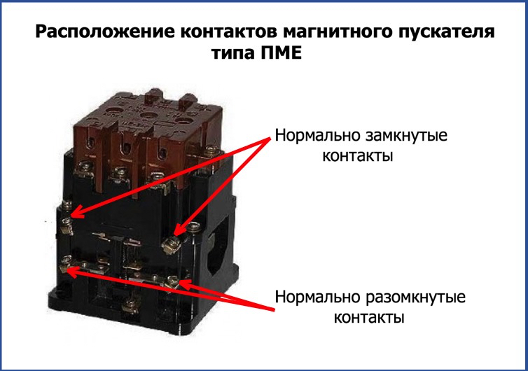
Contact groups of the magnetic starter
The following markings are used to designate the power contacts:
- 1L1, 3L2, 5L3 - input elements designed to supply power from a DC or AC line;
- 2Т1, 4Т2, 6Т3 - output contacts for connection to the load;
- 13NO – 14NO - auxiliary elements for self-picking help during engine operation not to hold the Start button constantly.
The load or power supply can be connected to any of the groups.
Stop key

Regardless of the modification, the starter for the electric motor is controlled using the "Stop" or "Start" button. Some models have a reverse mode.The stop button can be identified by its red color.
The normally closed contacts are mechanically connected to the stopper to allow the current to flow freely. Without pressing a key, the contacts are closed by a metal bar. For the device to stop, you need to press the button - it will open. In the absence of latching after releasing the button, the contacts will close.
For this reason, the electric motor is controlled using special circuits. To simplify installation, the device is mounted on a DIN rail.
Start key
The green or black button is mechanically connected to the normally open contacts. It differs from the stop key in the state of the contacts. After pressing it, the circuit is closed, and current flows through the contacts. The group of elements is held by a spring, which returns it to its original position.
Device types
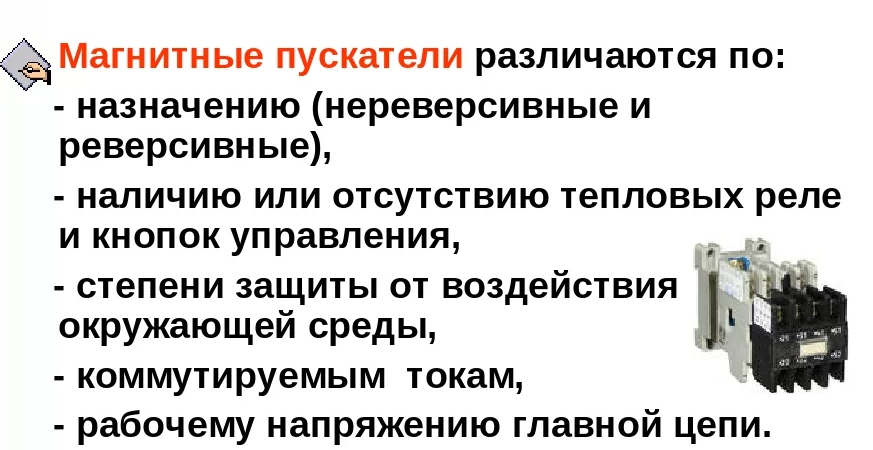
- Open type. Installed in panels, closed boxes and places protected from dust.
- Closed execution. Placed indoors, control buttons are located on the body.
- Dust-proof. Suitable for indoor and outdoor installation, as they are protected from dust and moisture by a special visor.
- Relay. A magnetic starter with a thermal relay protects the motor in conditions of short overloads on the line. The relay switch is combined with the device or connected to it.
- Three-phase. A feature of the three-phase starter is the inadmissibility of exceeding the starting current over the rating. If this is not the case, with the help of the device, the phase is restored and the uninterrupted operation of the engine is ensured at low starting current values.
With frequent overloads, the starter's winding may burn out.
Design versatility
The electromagnetic mechanism is located inside and is a fixed W-shaped core and a coil with a winding. The movable unit is an anchor connected to a traverse and plastic. It contains contact bridges with active elements. Springs are used for smooth closing.
The fixed group of contacts is soldered onto plates with screw terminals. With their help, you can connect a cable from an external line. Additional contacts are located on the side of the device.
Some models have a special cover for the main contact block.
Electric starters with thermal relays
Magnetic starters with thermal relays protect the motor from short-term overload. The indicators of the installation current can be set by means of a regulator - it is turned with a screwdriver. To prevent short circuits, models with a thermal relay are not used.
Degree of protection
Devices with IP54 protection are suitable for installation in open areas, in humid and dusty rooms. It is advisable to install modifications with IP20 protection inside the box. In addition to the numerical index, it is necessary to take into account the durability of the apparatus under conditions of frequent load drops.
The larger the numeric index, the less requirements for the installation of the starter.
Subtleties of connecting a 220 V device
A din-rail is used to connect a single-phase magnetic starter and prevent its vibrations. The device must not be placed next to rheostats or in a heated part of the box. The tinned end of the conductor connected to the device is bent in the form of a ring or the letter P. A layer of grease (technical Vaseline, Tsiatim) is applied to the aluminum cables. The device is switched on according to several schemes.
Classic
Suitable if the load sources are motors or heating elements. The scheme consists of several parts:
- Power.This includes contacts for three phases, an automatic switch (placed between the input and the power source).
- Load. A powerful consumer is required.
- Chain. It consists of a start and stop button, a coil, additional contacts, is thrown on a phase and zero.
The contacts of the starter are closed and voltage is supplied to the load after pressing the "Start" button. By pressing the stop button, the contacts are opened and the voltage is no longer supplied.
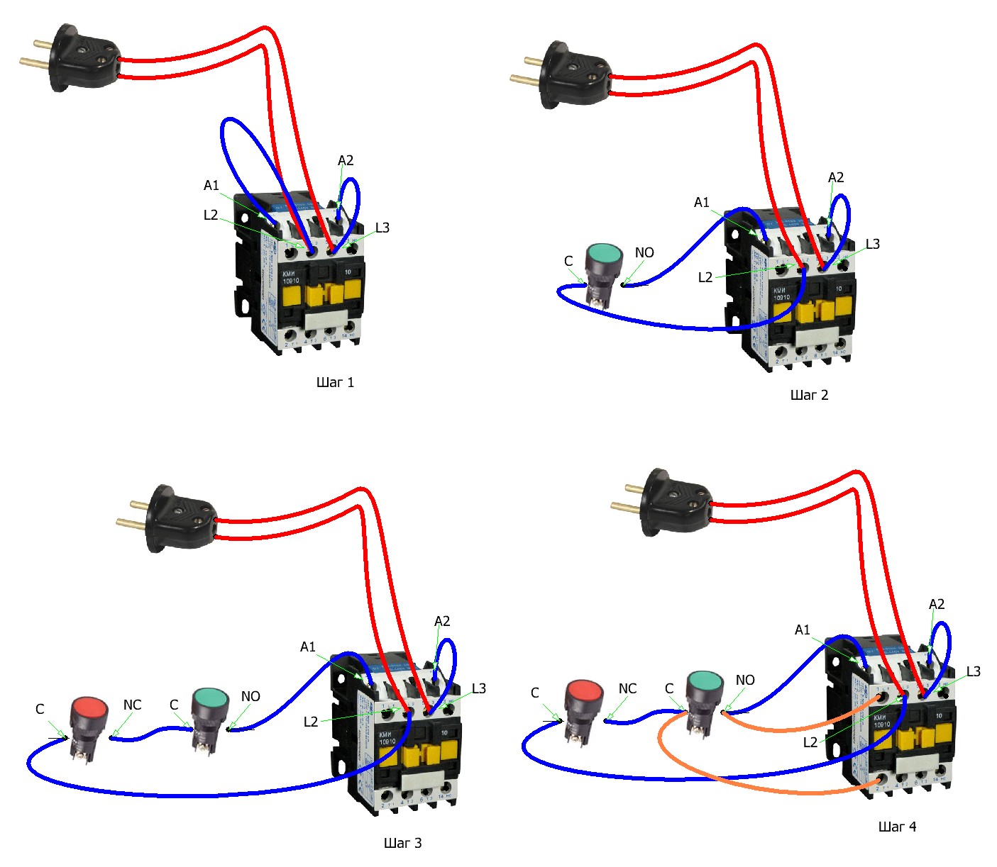
Power circuit specifics
The single-phase starter is powered through contacts A-1 and A-2. They are supplied with a voltage of 220 V, if the coil is designed for it. The phase is fed to A-2, the power source is fed to the elements at the bottom of the case. The voltage can be supplied from a wind generator, battery, diesel generator. To remove it, the terminals are used - T-1, T-2, T-3. The disadvantage of the circuit is the need to use a plug to turn the machine on or off.
How to change the control circuit
The power system of the device is not affected during the upgrade. They work according to the following principle:
- push-button station keys (in one casing) have normally open terminals at start-up and normally closed terminals at installation;
- the buttons are placed in front of the magnetic starter in a sequential position - Start and Stop;
- manipulations with contacts are carried out using a control pulse;
- the start button supplies voltage to the coil and generates a pulse;
- the key is supported by self-locking contacts supplying the coil with voltage;
- self-locking contacts open, the coil is self-replenished.
The magnetic starter stops after the last circuit is broken.
Connection to a three-phase network
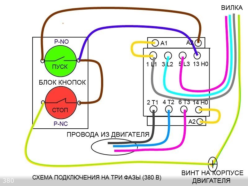
The power circuit is slightly upgraded. The phases are supplied to the inputs L1, L2, L3, the load is supplied to T1, T2, T3.
This circuit is suitable for an asynchronous motor.
Service specifics
For proper maintenance, it is necessary to disassemble the instrument with faults. Increased temperature readings are the consequences of turn-to-turn closures of the coil, which needs to be changed. Overheating is also observed when contacts are poorly connected, worn out or overloaded.
If the machine hums, the armature does not fit tightly to the core, is dirty or damaged. If active parts are seized or the voltage drops by 15%, it is necessary to check the tightness of the contacts.
Magnetic starters are used to protect induction motors. Before connecting the device, you need to understand the scheme of its operation, the possibility of integration with a thermal relay and the specifics of changing the control mechanism.